| Mars Clock | ||||||||||||||||
| Main | Construction | Operation | Schematics | Code | HowTo | Other Projects | ||||||||||
Finding the right enclosure for a project is often surprisingly difficult. You can make a nice box yourself if you have the tools, or you can buy a ready-made enclosure from places like RadioShack. My favorite approach, however, is to give new life to some old device - a modem, a computer mouse, whatever, - then to take out what I don't need and to keep anything I can re-use. In this case, a friend found for me this beautiful dialup modem from a long-gone era:
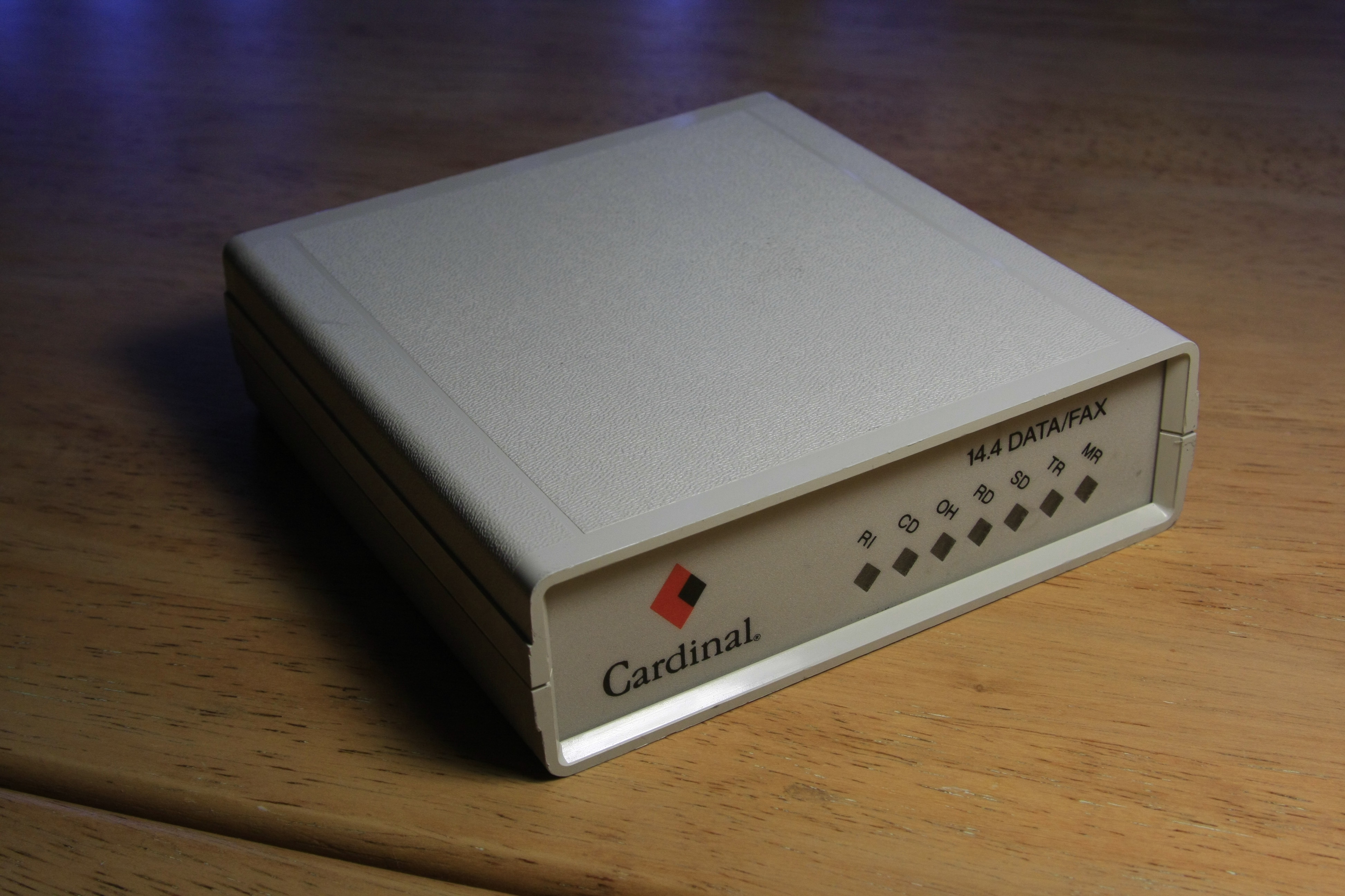
The junk electronic shop sold it for just $2.00 - way better than hobby shop enclosures. As a bonus, it had all the connectors I might need, and significant part of the electronics of the modem can be reused.
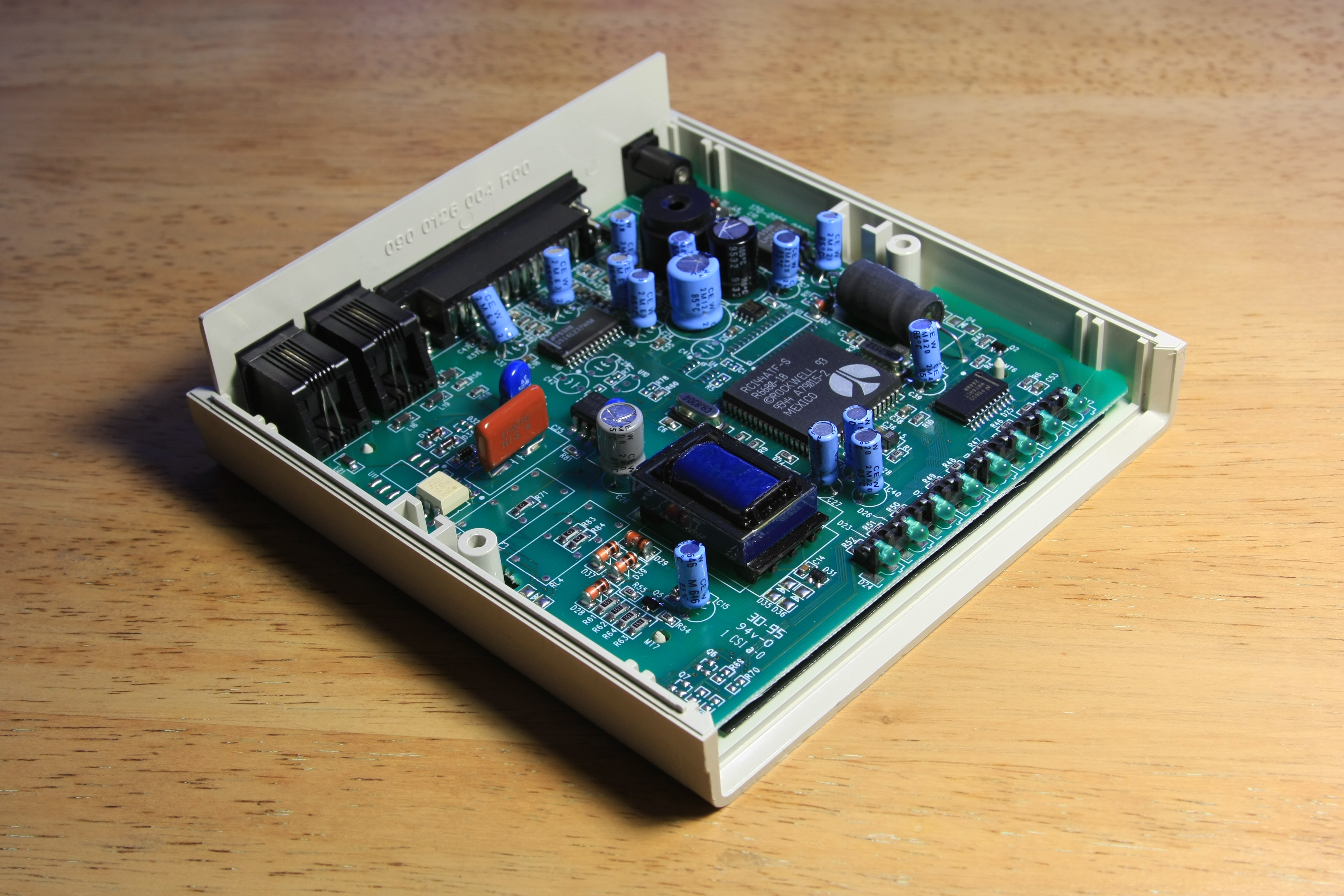
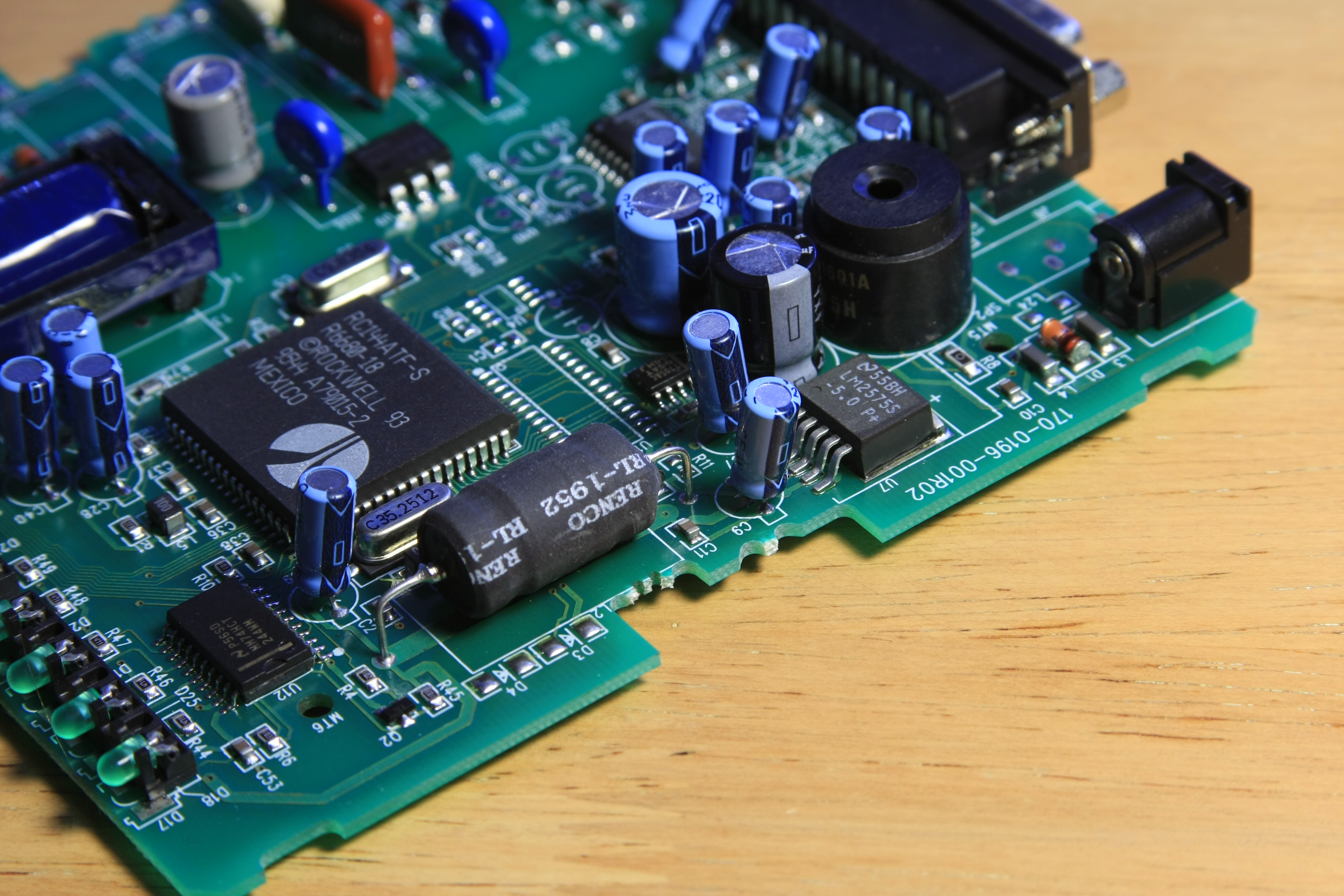
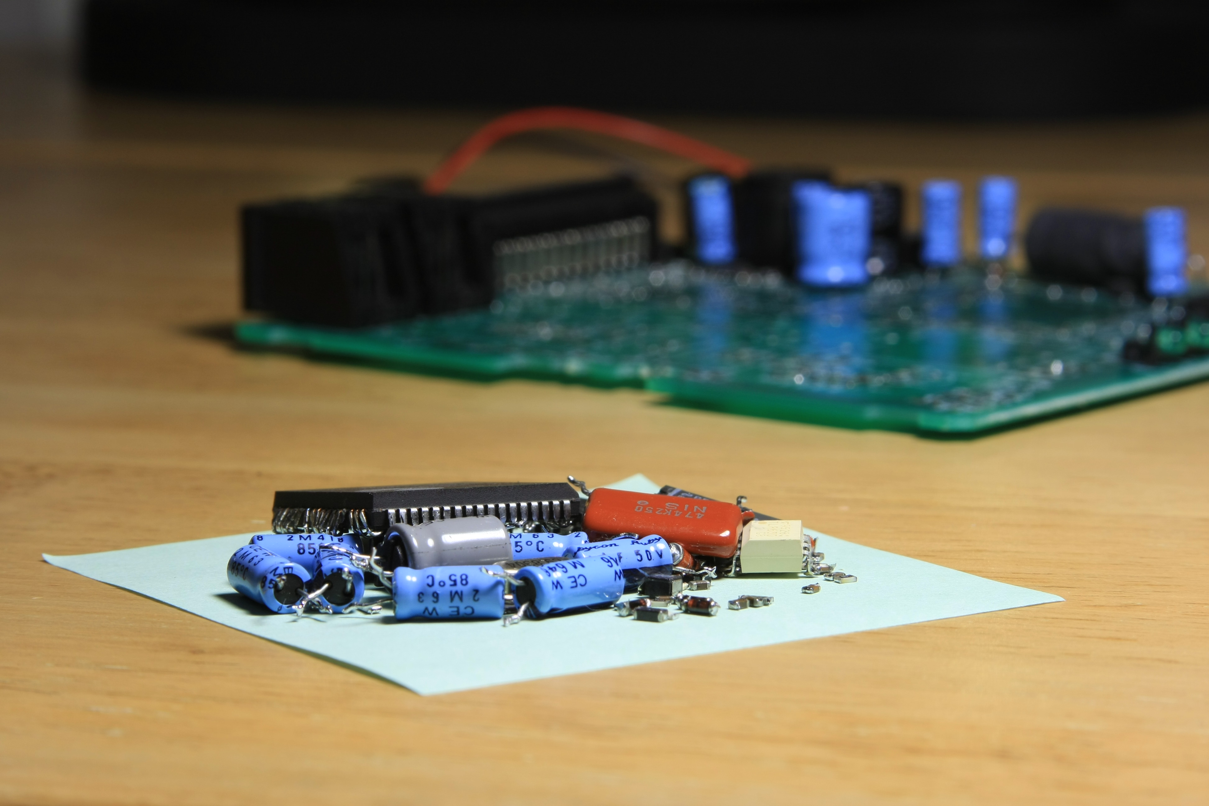
Time to take out the 10x magnifying glass and reverse engineer the schematics for the power supply on the board, and the amplifier circuits for the internal speaker. Another potentially useful thing are the LEDs in front, along with their driver chip (I haven't used the LEDs in this project yet, but decided to keep them, just in case). The rest should be taken out.
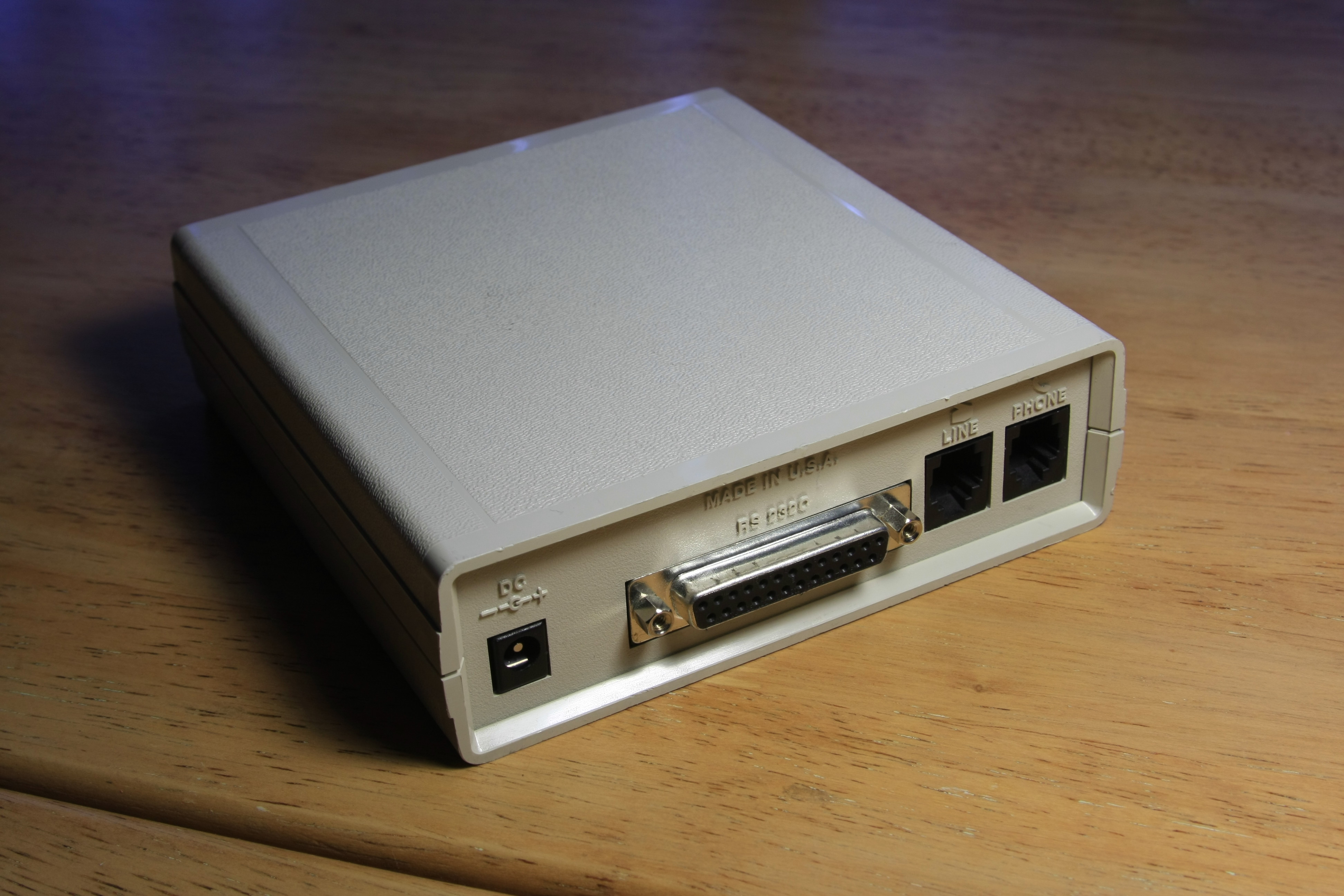
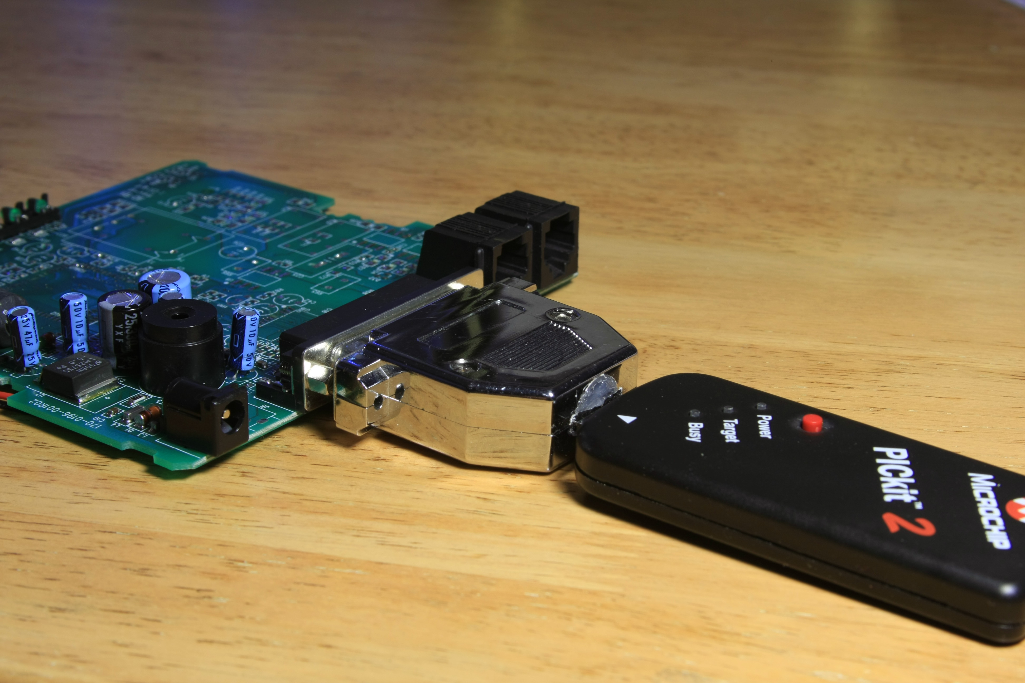
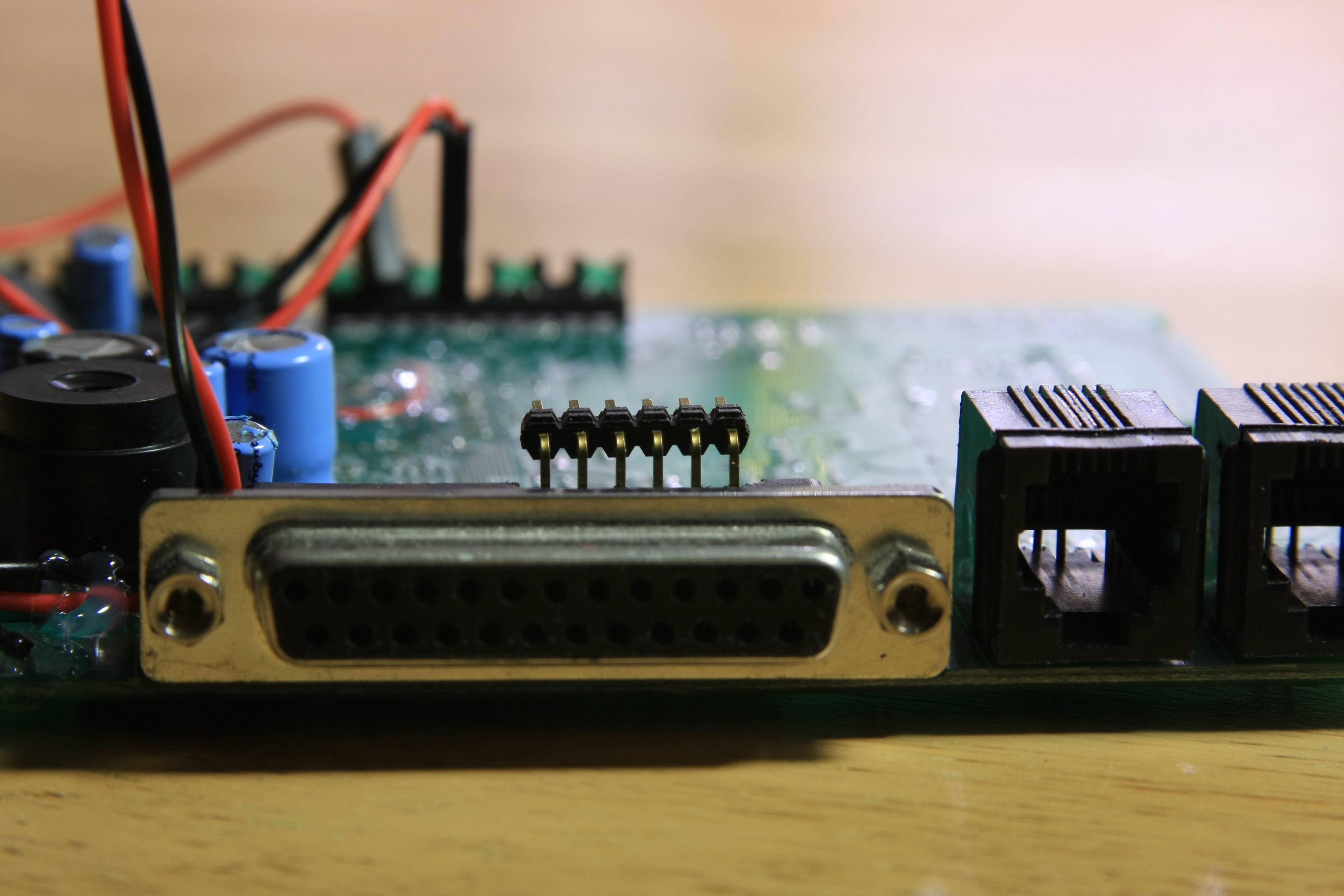
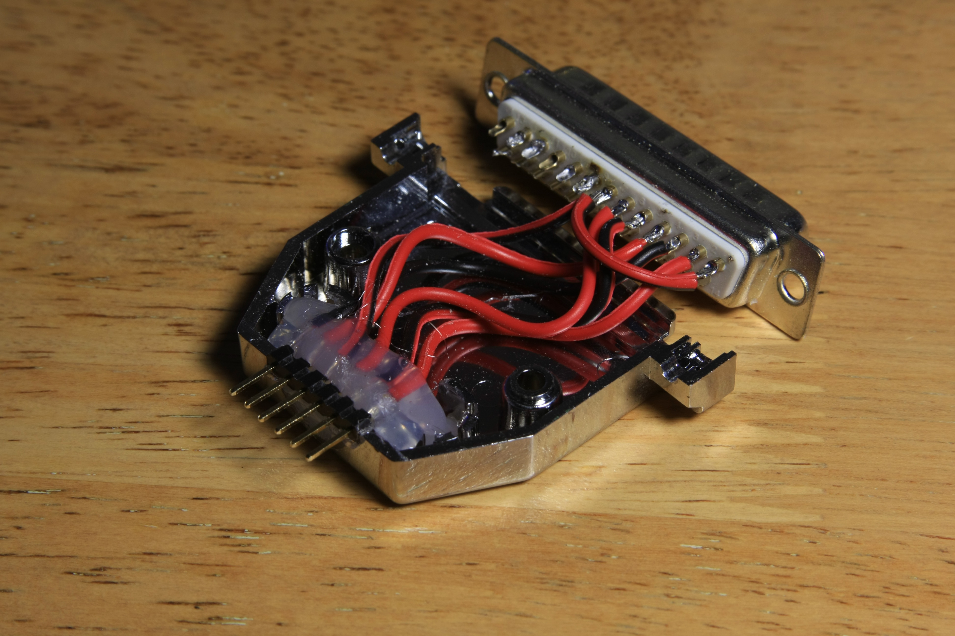
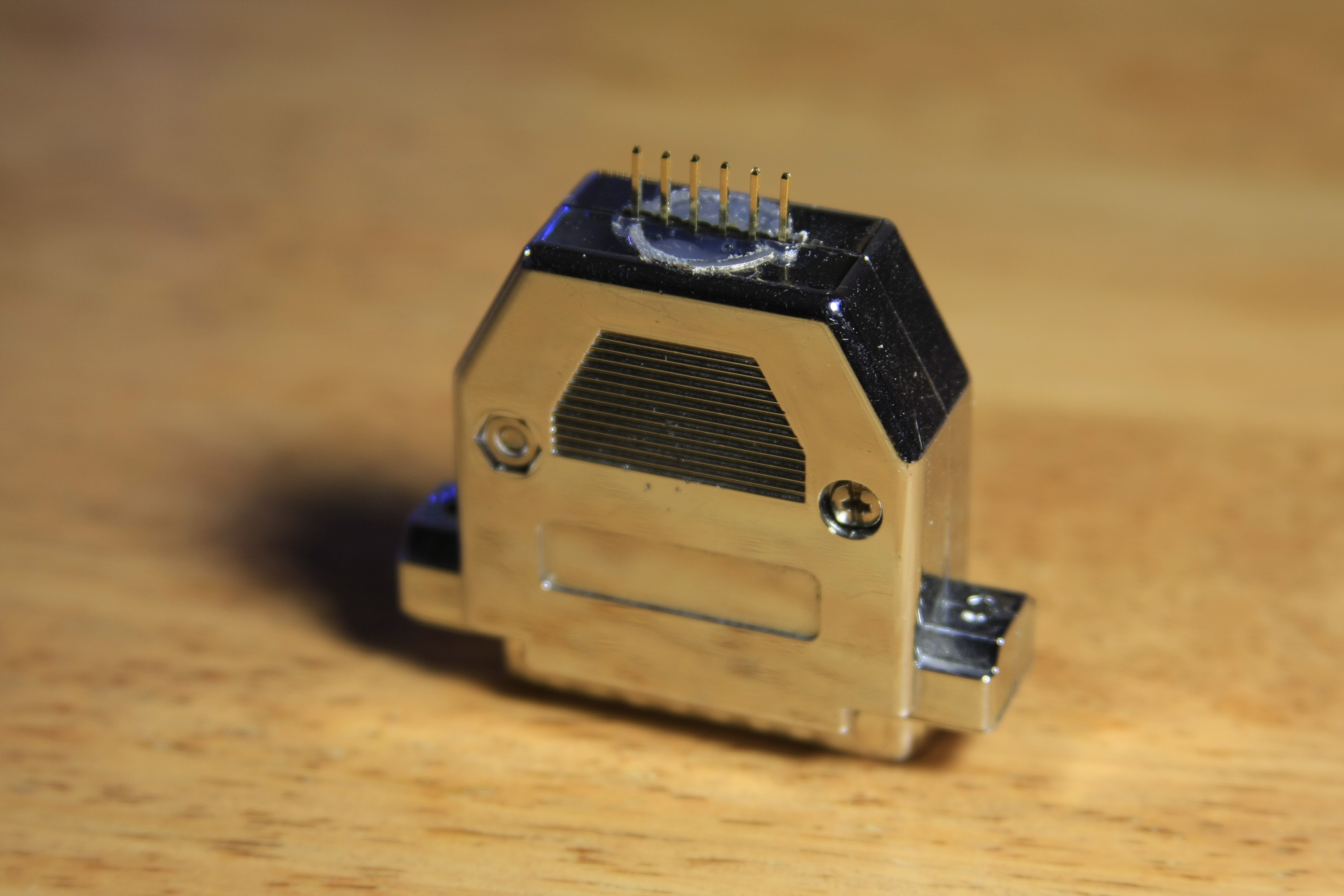
Time to decide what to do about the ports at the back. The main connector can be used to re-program the PIC without taking it out of the box. To do so, I attached some pin connectors to the internal side of the DB-25 leads so the microcontroller board can be plugged in there later:
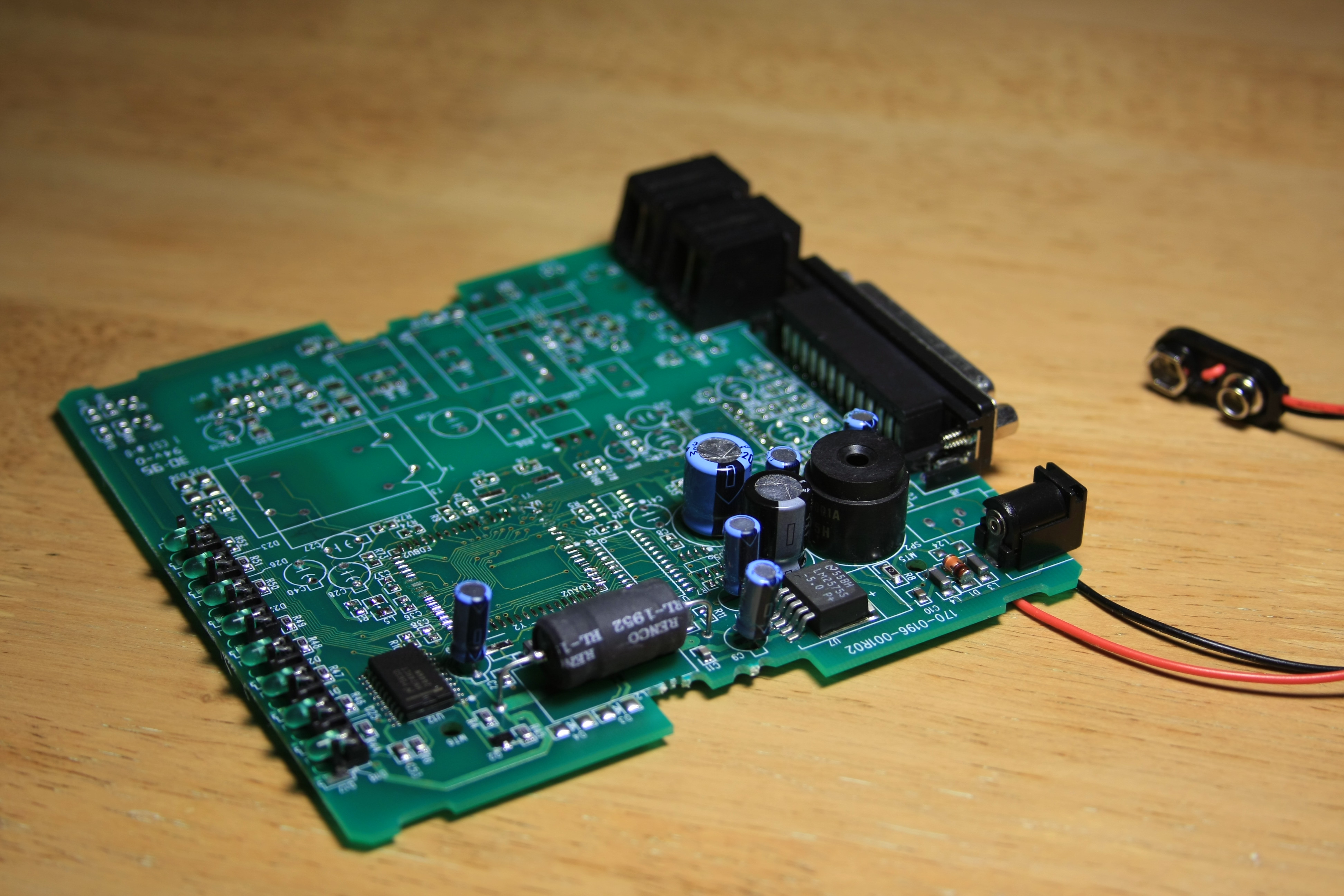
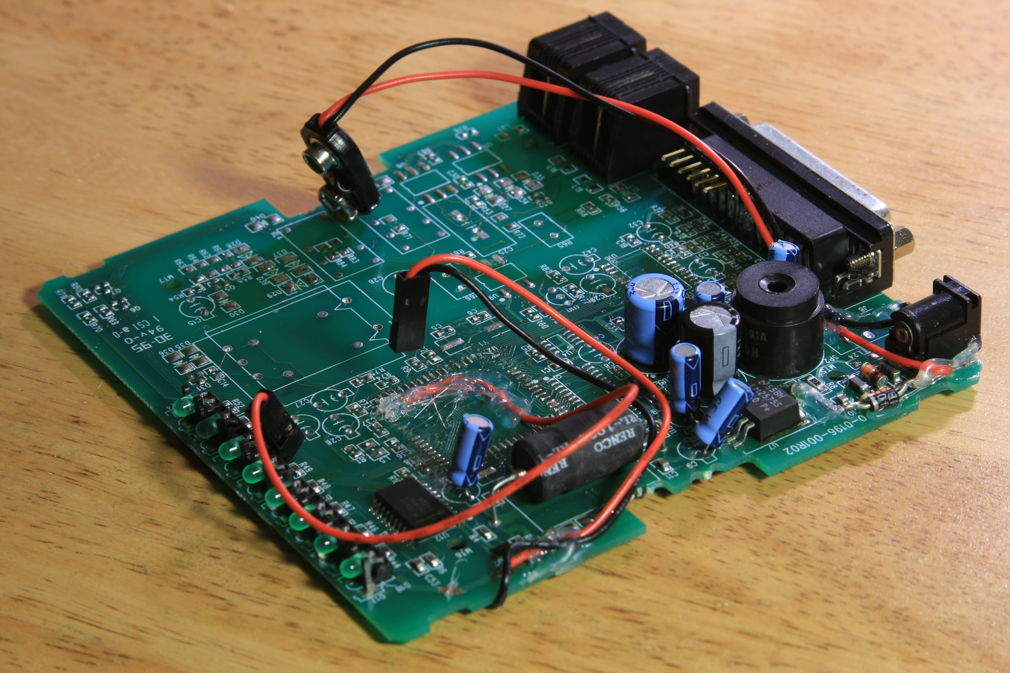
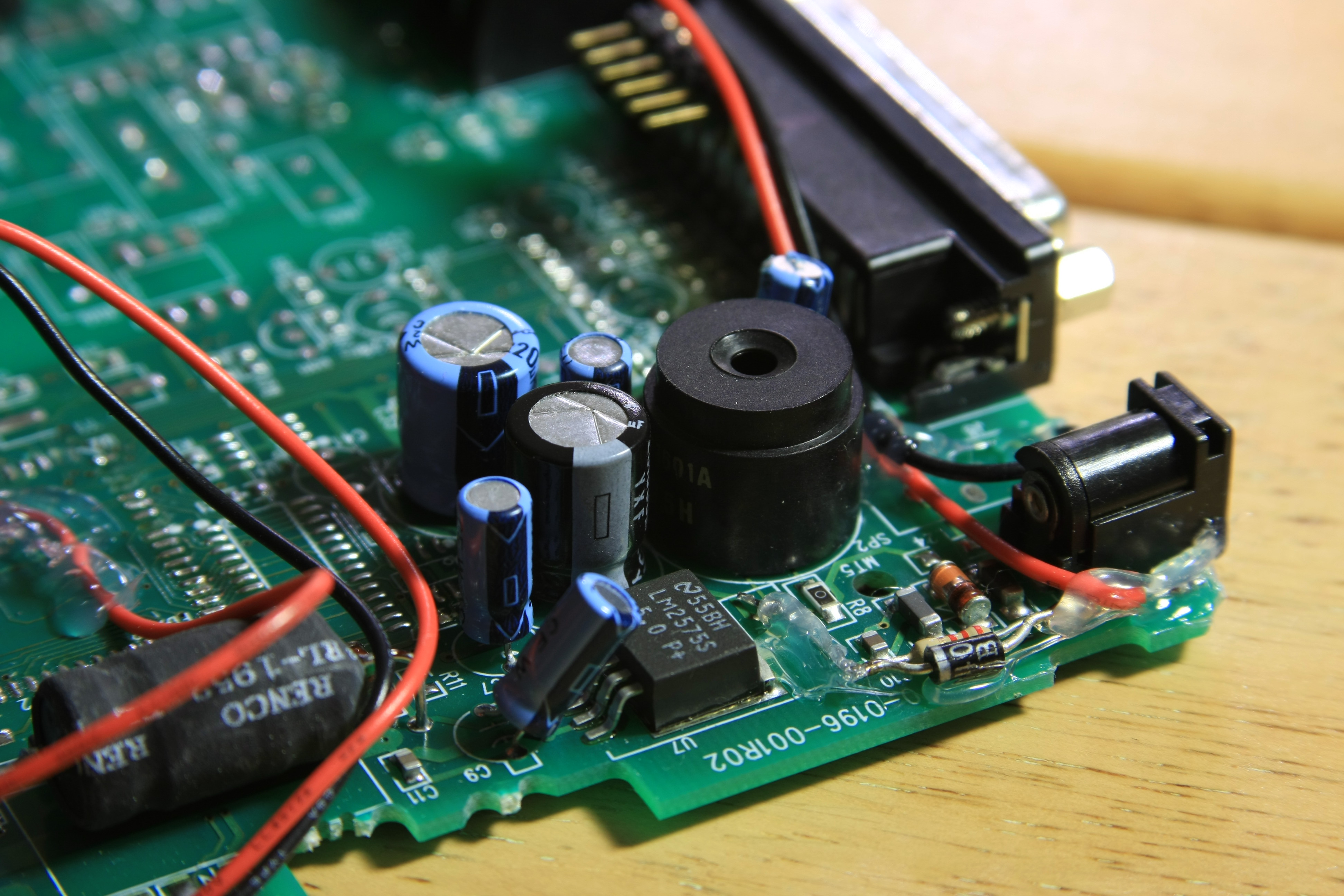
Next comes putting connectors to tap the stabilized 5V of the modem's power supply electronics. Another connector attaches to the modem's internal speaker amplifier (an easy to find LM386). Finally, I added a 9V connector for the rechargeable battery, along with a simple trickle-charger composed of a 2.2k resistor and a diode glued to the modem board:
To plug it to the PICKit2 programmer, I took apart a printer cable and did some very mean things to it:
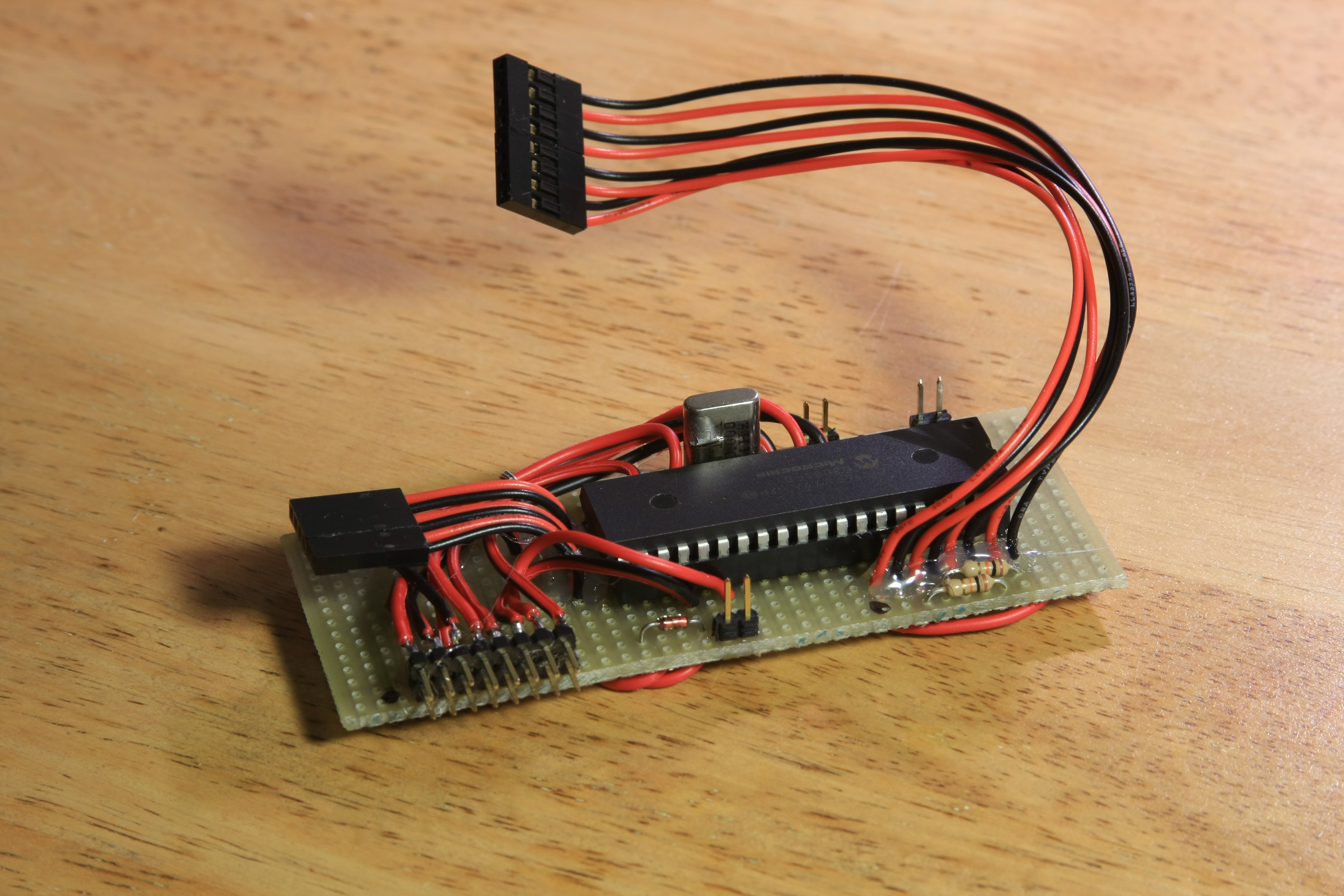
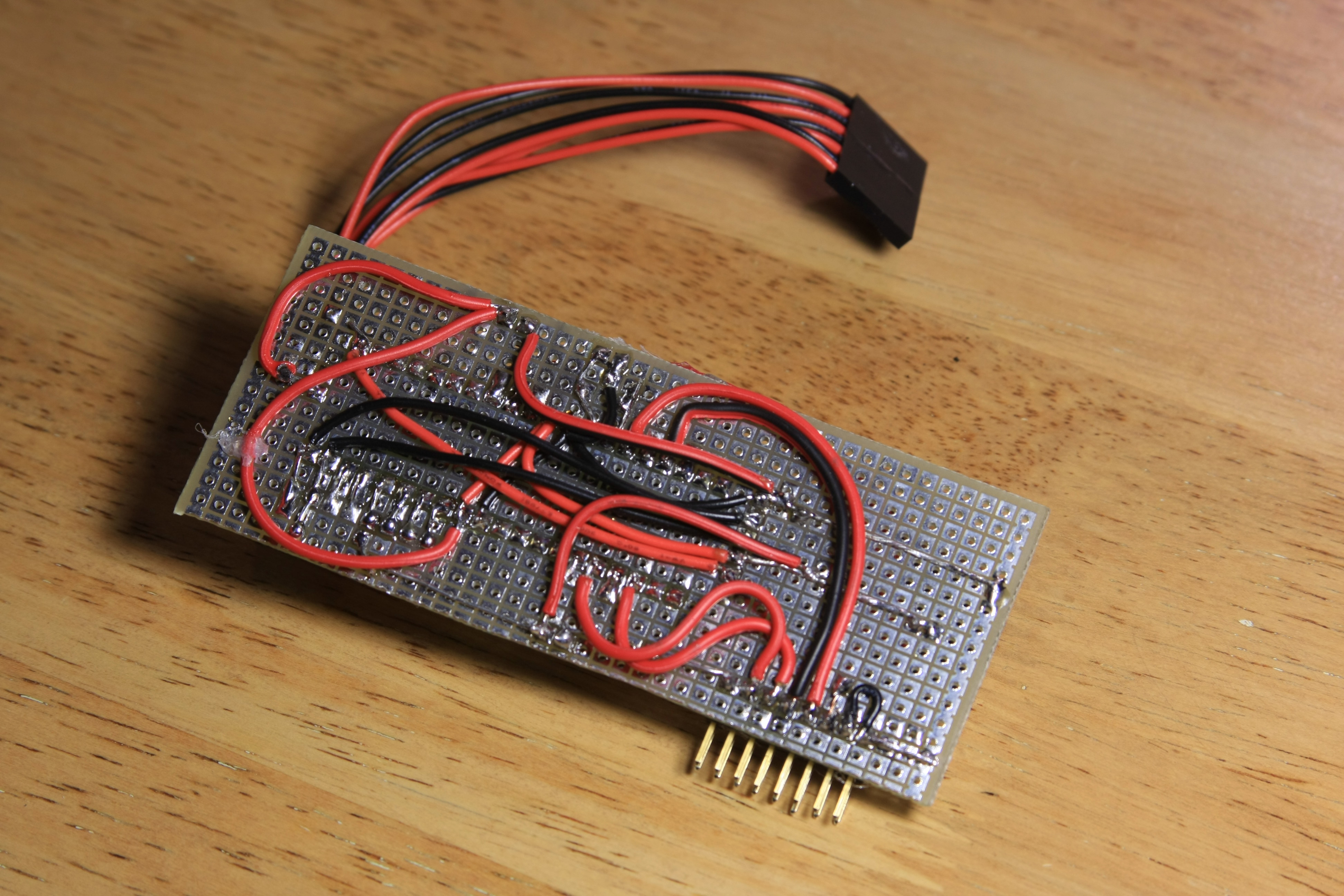
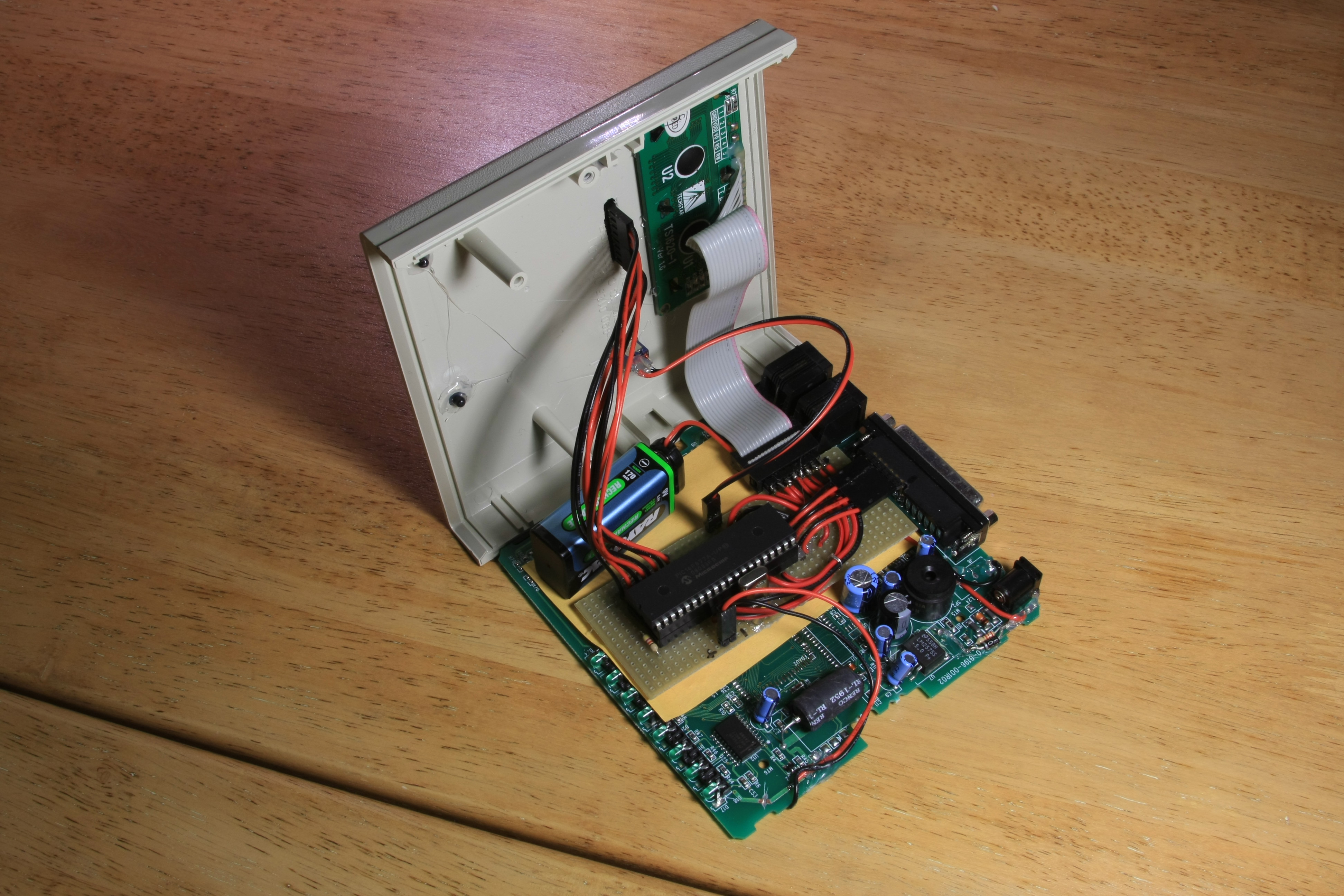
The board where the PIC and the rest of the electronics will sit is quite simple. Since we already have the speaker amplifier and the power supply, what's left is mostly connecting wires. Here is the board, in all its red-and-black glory:
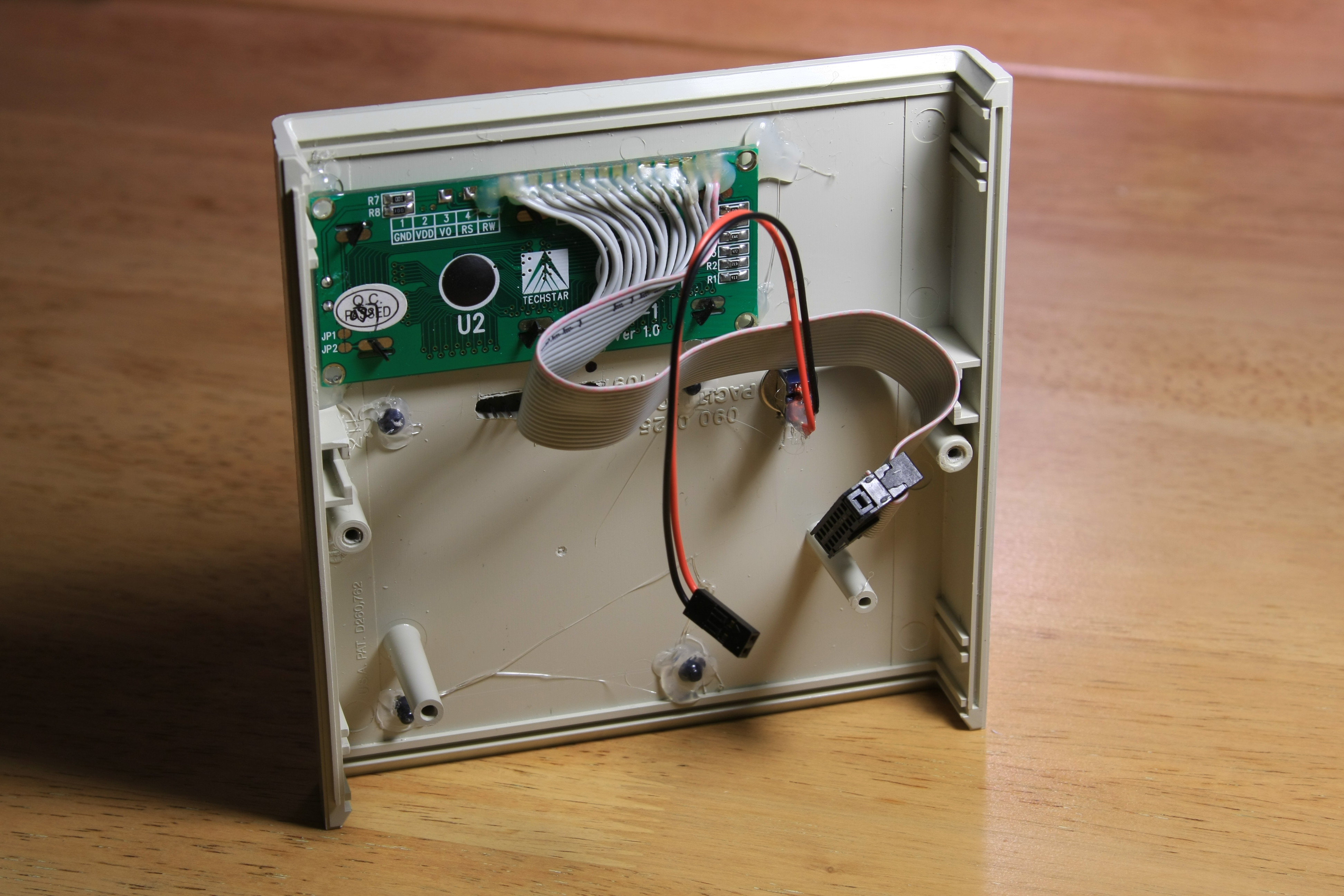
Time for some drilling and filing to attach the keyboard and the LCD module with its backlight switch. Attaching the keyboard and the backlight switch was easy. Making sure that the opening for the LCD module is the exactly right size and accurately positioned was not. But with some care, the end result was quite satisfactory:
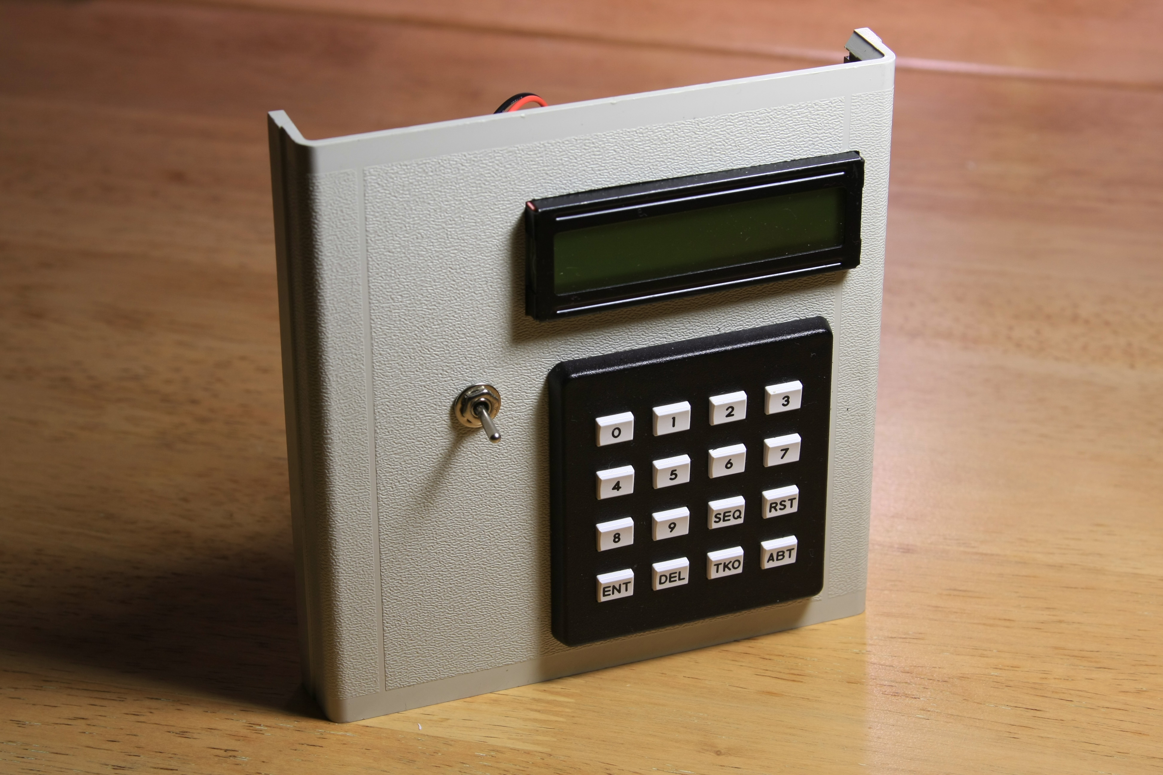
It starts to look like Monster Martian Clock already. After some hard programming, a few sleepless nights, and just a bit of magic, it is finally complete:
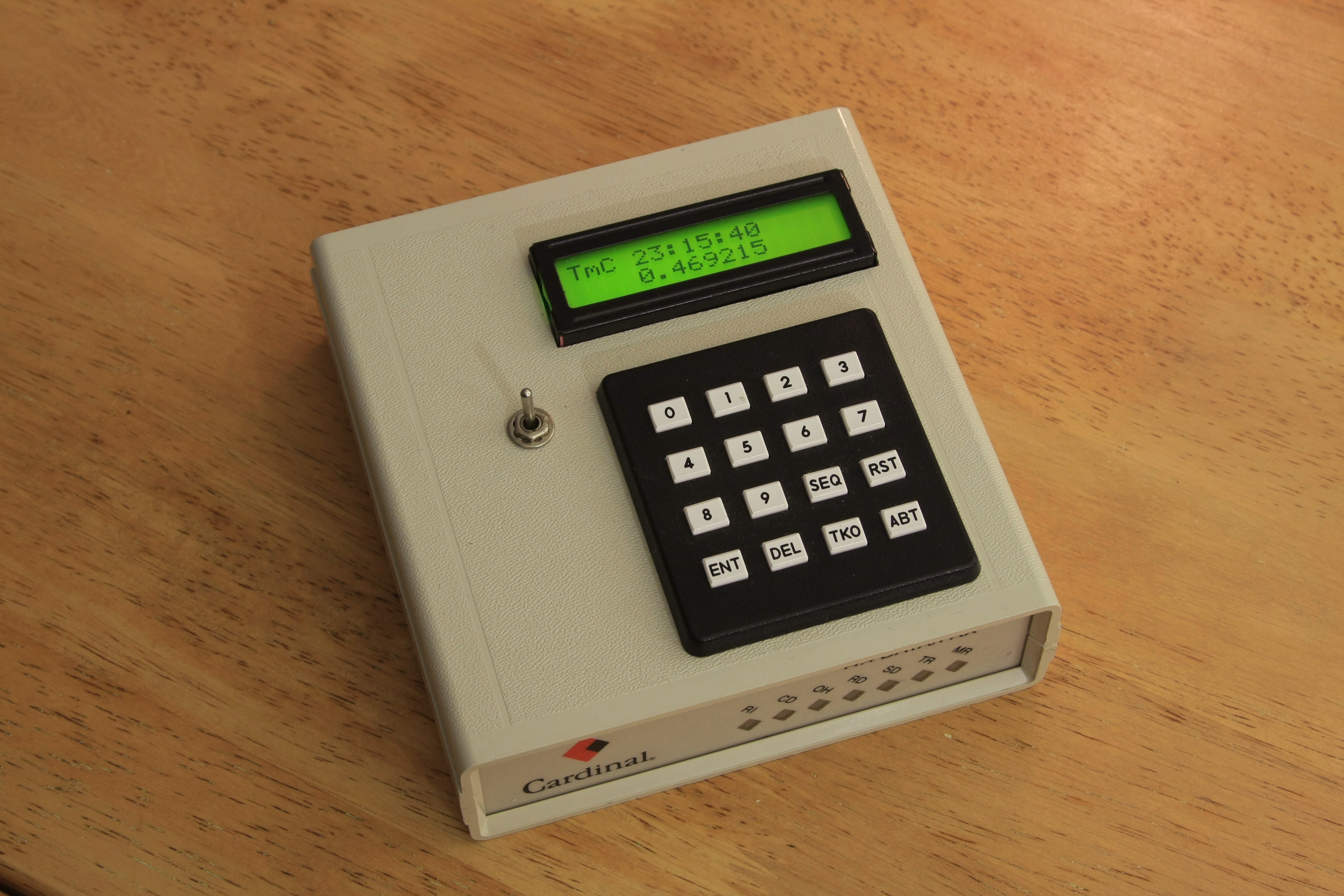
If I try to take it with me on a trip they will evacuate the airport, for sure!